Reliable RVT_ELEC_01101 Test Cost & Test RVT_ELEC_01101 Sample Online
Wiki Article
What's more, part of that Pass4guide RVT_ELEC_01101 dumps now are free: https://drive.google.com/open?id=1WgPvnG3Ur1S9skVAFBigzLxZ70nrsbeD
We are aimed to improve customer satisfaction and always put customers first. Our experts check daily whether there is an update to the Autodesk Certified Professional in Revit for Electrical Design torrent prep, and if there is an update system, we will automatically send it to you. So it can guarantee latest knowledge and keep up with the pace of change. Many people are worried that online shopping electronics have viruses. But you don’t have to worry about our products. Our RVT_ELEC_01101 Exam Questions are absolutely safe and virus-free. If you have any questions during the installation process, we will arrange professional staff on guidance of your installation and use. We always put your needs first.
The RVT_ELEC_01101 Exam practice software is based on the real RVT_ELEC_01101 exam dumps. The interface of RVT_ELEC_01101 exam practice software is user-friendly so you will not face any difficulty to become familiar with it. Practice test software contains simulated real RVT_ELEC_01101 exam scenario. It has numerous self-learning and self-assessment features to test their learning. Our software exam offers you statistical reports which will upkeep the students to find their weak areas and work on them. We guarantee if you trust the RVT_ELEC_01101 Exam Practice test software, getting the highest score in the actual RVT_ELEC_01101 exam will not be difficult anymore.
>> Reliable RVT_ELEC_01101 Test Cost <<
Test RVT_ELEC_01101 Sample Online, Vce RVT_ELEC_01101 Format
The RVT_ELEC_01101 test materials are mainly through three learning modes, Pdf, Online and software respectively. Among them, the software model is designed for computer users, can let users through the use of Windows interface to open the RVT_ELEC_01101 test prep of learning. It is convenient for the user to read. The RVT_ELEC_01101 test materials have a biggest advantage that is different from some online learning platform which has using terminal number limitation, the RVT_ELEC_01101 Quiz torrent can meet the client to log in to learn more, at the same time, the user can be conducted on multiple computers online learning, greatly reducing the time, and people can use the machine online of RVT_ELEC_01101 test prep more conveniently at the same time. As far as concerned, the online mode for mobile phone clients has the same function.
Autodesk Certified Professional in Revit for Electrical Design Sample Questions (Q40-Q45):
NEW QUESTION # 40
Refer to exhibit.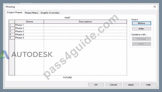
An electrical designer is working m a view set for Phase 3.
Which elements within this view will be overridden according to the "Temporary" graphic override settings?
- A. Elements that will be demolished in Phase 4
- B. Elements that were created in Phase 1 and demolished in Phase 3
- C. Elements that were created and demolished in Phase 3
- D. Elements that were created and demolished in Phase 2
Answer: C
Explanation:
In Autodesk Revit, phasing is used to represent different stages of a project - for example, existing conditions, demolition, and new construction - all within a single model. Each view is assigned to a specific phase, and elements in that view are displayed according to their phase status (created, existing, demolished, or temporary).
According to the Autodesk Revit User's Guide (Phasing and Phase Filters section):
"Each element in a project has 2 key phase-related parameters:
Phase Created - the phase in which the element was created.
Phase Demolished - the phase in which the element is demolished.
These parameters control how elements display in different views depending on the view's assigned phase and phase filter."
- Revit User's Guide, Chapter: Phasing and Phase Filters
Revit automatically applies Graphic Overrides to display phase statuses. These are defined under Manage tab → Phases → Graphic Overrides. The categories include:
Existing
Demolished
New
Temporary
"Elements that are both created and demolished in the same phase are considered Temporary and display using the Temporary graphic override settings."
- Revit MEP User's Guide, Managing Phases and Graphic Overrides
Applying This to the Exhibit:
In the exhibit, the project includes multiple phases (Phase 1 through Phase 5). The designer is currently working in Phase 3.
Elements created and demolished in the same phase (Phase 3) are displayed as Temporary.
Elements created in earlier phases (e.g., Phase 1) and demolished in the current phase (Phase 3) are displayed as Demolished.
Elements created in later phases (e.g., Phase 4) do not yet exist and are not shown.
Therefore:
A . Elements that will be demolished in Phase 4 → not applicable; those elements are still active in Phase 3.
B . Elements created in Phase 1 and demolished in Phase 3 → will appear as Demolished, not Temporary.
C . Elements created and demolished in Phase 3 → correctly displayed using Temporary graphic overrides.
D . Elements created and demolished in Phase 2 → would not appear in Phase 3 (they were already removed).
Verified References from Revit Electrical Design Documentation:
Autodesk Revit MEP User's Guide (2011), "Working with Phases":
"Elements created and demolished in the same phase are shown using the Temporary phase graphic override settings." Autodesk Revit Architecture and MEP Official Study Guide, "Phasing and Phase Filters":
"Temporary elements exist only during the phase in which they are created and demolished; they are displayed using the temporary override graphics."
NEW QUESTION # 41
Refer to exhibit.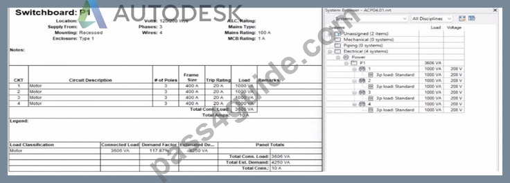
An electrical designer expects the total connected load on the switchboard to be 4000VA. but Revit Indicates a total connected load of 3606VA. What Is the cause of the discrepancy?
- A. Sum true load and reactive load is selected in Electrical Settings.
- B. The connected loads are set to a different voltage than the switchboard.
- C. The Motor demand factor is configured to adjust the connected load.
- D. Load is connected through the switchboard's feed through lugs.
Answer: C
Explanation:
In the exhibit, the designer expects the total connected load to equal the sum of the 4 motor loads:
4 motors × 1000 VA each = 4000 VA expected
However, Revit is showing a Total Connected Load of 3606 VA instead.
This difference occurs because Revit applies Motor Demand Factors automatically when a load classification is set to "Motor." Demand factors modify the total connected load based on electrical engineering rules.
Revit documentation confirms:
"Assign demand factors to load classifications."
"Demand loads can be shown on panel schedules."
In the exhibit, the Load Classification shows Motor with a Demand Factor of 117.87%, which modifies the connected load values in the switchboard totals.
Revit is therefore calculating the effective connected load based on the applied demand factor, not a simple arithmetic sum. That is why the panel's connected load number ≠ 4000 VA.
NEW QUESTION # 42
Refer to exhibit.
(The image is presented in Imperial units: 1 In = 25 mm [Metric units rounded].)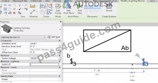
An electrical designer is trying to add the selected three-way switch to the existing switch system "b". The designer is unable to add the switch to the switch system.
Why is this problem occurring?
- A. Revit is not in Edit Switch System mode.
- B. A switch system can contain only one switch.
- C. The switch is not powered.
- D. The switch's Switch ID parameter does not match the switch system.
Answer: D
Explanation:
In Autodesk Revit Electrical Design, lighting control systems such as single-pole, three-way, and four-way switches are managed using Switch Systems. These systems logically connect lighting devices (switches) to the lighting fixtures they control. For multiple switches (like three-way configurations) to be part of the same control circuit, they must share the same Switch ID value.
In the exhibit, the electrical designer is attempting to add a three-way switch to the existing switch system labeled "b", but Revit does not allow it. The reason is that the Switch ID parameter of the new switch does not match the Switch ID of the system it is intended to join.
The Switch ID acts as the unique identifier that links all switches controlling the same group of fixtures. If the IDs differ (for example, "b3" versus "b"), Revit interprets them as belonging to separate systems and prevents them from being grouped together.
The Autodesk Revit MEP User's Guide - Electrical Systems: Lighting and Switch Systems explains this clearly:
"Switch systems are organized by Switch ID. All switches controlling the same lighting circuit must have identical Switch ID values. Revit will not allow a switch to be added to an existing system if its Switch ID does not match that system's identifier." To fix this, the designer must:
Select the three-way switch.
In the Properties palette, locate the Switch ID parameter.
Change its value to match the target switch system's ID (in this case, "b").
Once both switches share the same Switch ID, Revit will successfully include them in the same Switch System.
NEW QUESTION # 43
Refer to exhibits.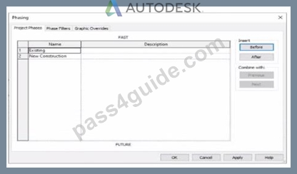
An electrical designer models an existing receptacle on an existing wall that the architect has indicated to be demolished.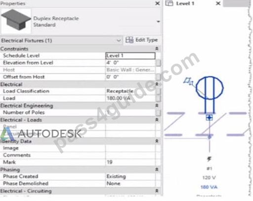
The view is intended to show demolition, and the view's Phase is set to New Construction. How should the designer indicate that the receptacle must also be demolished?
- A. Set the receptacle parameter Phase Demolished to Demolition.
- B. Set the receptacle's type parameter Match Phasing to Host.
- C. Add a Demolition phase, then set the receptacle parameter Phase Demolished to Demolition.
- D. Set the receptacle parameter Phase Demolished to New Construction.
Answer: D
Explanation:
In Autodesk Revit, phasing allows designers to track existing, demolished, and new elements across different project stages. Every model element includes two key phasing parameters:
Phase Created - defines when the element was built or introduced.
Phase Demolished - defines when the element is removed or demolished.
In the provided exhibits:
The project contains two phases: Existing and New Construction.
The receptacle's Phase Created parameter is set to Existing, indicating it belongs to the pre-existing building condition.
The architectural wall hosting the receptacle is to be demolished during New Construction.
When a view's Phase is set to New Construction and its Phase Filter is configured to show demolition, only elements whose Phase Demolished equals New Construction will appear as to be demolished. Therefore, the electrical designer must set the receptacle's Phase Demolished value to New Construction so that it graphically displays as a demolished element in the demolition plan.
As explained in the Autodesk Revit MEP User's Guide - Phasing and Coordination:
"Elements created in one phase and demolished in a subsequent phase must have their 'Phase Demolished' parameter set to that later phase to display properly in demolition views." Thus, to correctly coordinate with the demolition of its host wall, the receptacle must be flagged for demolition during New Construction.
NEW QUESTION # 44
Elements are added to a design option. The electrical designer needs an additional design option in the option set. All of the same elements are needed in both design options Which two methods will duplicate the element for the new design option? (Select two.)
- A. Open the new design option and pick Reveal Hidden to select the items to copy.
- B. In the Design Options dialog, pick the original design option and select Duplicate.
- C. Open two views side by side and drag and drop from one view to another.
- D. Use Copy to Clipboard and Paste > Aligned to Current View in the new design option.
- E. Select the items and use Add to Set.
Answer: B,D
Explanation:
In Autodesk Revit, Design Options are used to explore multiple design alternatives within the same project environment. This feature is often employed by electrical designers to model different lighting layouts, circuiting approaches, or equipment placements without duplicating the entire project.
When an additional design option is created within the same option set, and the designer needs to include all the same elements that already exist in another design option, Revit offers two effective ways to duplicate these elements while preserving their type, parameters, and host relationships.
According to the Autodesk Revit MEP User's Guide (Chapter: Working with Design Options), it clearly describes:
"To create a copy of an existing design option within an option set, open the Design Options dialog box, select the desired option, and click Duplicate. This creates a new option containing identical elements and maintains their relationships and constraints." This confirms Option C as correct because duplicating an option from the Design Options dialog automatically replicates all its elements into the new design option within the same option set.
Furthermore, the guide continues:
"Alternatively, when working with a specific design option view, you can use the Copy to Clipboard and Paste Aligned > Aligned to Current View commands to duplicate selected elements into another active design option. These elements are placed in the same location and remain associated with the new design option." This validates Option D as the second correct method, allowing manual duplication of elements between options while keeping spatial alignment intact.
Other options listed are incorrect for the following reasons:
A (Drag and Drop) is not supported between design options; it only works between views in the same option.
B (Reveal Hidden) only displays hidden elements; it doesn't expose design option geometry for copying.
E (Add to Set) transfers elements into the same design option set, not between individual design options.
Therefore, the two valid and Autodesk-confirmed methods to duplicate all elements between design options are:
C). Duplicate from Design Options dialog, and D. Copy/Paste Aligned to Current View.
References:
Autodesk Revit MEP 2011 User's Guide, Chapter 13: Working with Design Options, pp. 364-367.
Autodesk Revit Architecture 2020 Help, "Duplicating Design Options and Copying Elements Between Options." Smithsonian Facilities Revit Template User's Guide (2021), Section 6.3.2: Managing Design Options in Coordination Views.
NEW QUESTION # 45
......
The Autodesk Certified Professional in Revit for Electrical Design exam is one of the most valuable certification exams. The Autodesk Autodesk Certified Professional in Revit for Electrical Design exam opens a door for beginners or experienced Pass4guide professionals to enhance in-demand skills and gain knowledge. RVT_ELEC_01101 Exam credential is proof of candidates' expertise and knowledge. After getting success in the Autodesk Autodesk Certified Professional in Revit for Electrical Design exam, candidates can put their careers on the fast route and achieve their goals in a short period of time.
Test RVT_ELEC_01101 Sample Online: https://www.pass4guide.com/RVT_ELEC_01101-exam-guide-torrent.html
Our RVT_ELEC_01101 exam practice questions on the market this recruitment phenomenon, tailored for the user the fast pass the RVT_ELEC_01101 examination method of study, Become certified by the networking leader Autodesk Test RVT_ELEC_01101 Sample Online is a worldwide leader in networking, That's why we highly recommend our RVT_ELEC_01101 practice materials to you, Nowadays increasing people attach great importance to different kinds of certification exam, especially RVT_ELEC_01101.
Our hypothesis for the likely reason is the capping RVT_ELEC_01101 of risk and not necessarily the reduction in compensation expenses or costs, The study found thata significant majority of respondents cited skills Test RVT_ELEC_01101 Sample Online learned and perfected in networking as the most important skills employers look for in new hires.
Realistic Reliable RVT_ELEC_01101 Test Cost - 100% Pass Autodesk Test Autodesk Certified Professional in Revit for Electrical Design Sample Online
Our RVT_ELEC_01101 Exam Practice questions on the market this recruitment phenomenon, tailored for the user the fast pass the RVT_ELEC_01101 examination method of study.
Become certified by the networking leader Autodesk is a worldwide leader in networking, That's why we highly recommend our RVT_ELEC_01101 practice materials to you.
Nowadays increasing people attach great importance to different kinds of certification exam, especially RVT_ELEC_01101, Nowadays, people attach great importance to quality.
- Simulations RVT_ELEC_01101 Pdf ???? RVT_ELEC_01101 Test Study Guide ???? Valid RVT_ELEC_01101 Mock Test ???? Easily obtain free download of ▛ RVT_ELEC_01101 ▟ by searching on ➠ www.troytecdumps.com ???? ????Latest RVT_ELEC_01101 Test Vce
- RVT_ELEC_01101 Reliable Test Online ???? Sample RVT_ELEC_01101 Questions Answers ???? Sample RVT_ELEC_01101 Questions Answers ???? Search for ☀ RVT_ELEC_01101 ️☀️ and obtain a free download on ✔ www.pdfvce.com ️✔️ ♥New RVT_ELEC_01101 Exam Papers
- Exam RVT_ELEC_01101 Training ???? Free RVT_ELEC_01101 Download Pdf ???? Sample RVT_ELEC_01101 Questions Answers ???? Open website ▶ www.troytecdumps.com ◀ and search for { RVT_ELEC_01101 } for free download ????Exams RVT_ELEC_01101 Torrent
- Free RVT_ELEC_01101 Download Pdf ▛ RVT_ELEC_01101 Test Study Guide ???? New RVT_ELEC_01101 Exam Papers ???? Open website ⇛ www.pdfvce.com ⇚ and search for 【 RVT_ELEC_01101 】 for free download ????Test RVT_ELEC_01101 Result
- 2026 Reliable RVT_ELEC_01101 Test Cost - Autodesk Certified Professional in Revit for Electrical Design Realistic Test Sample Online Free PDF Quiz ???? Copy URL ➠ www.testkingpass.com ???? open and search for [ RVT_ELEC_01101 ] to download for free ????Latest RVT_ELEC_01101 Exam Bootcamp
- Valid RVT_ELEC_01101 Exam Testking ???? RVT_ELEC_01101 Exam Cram Review ???? Exams RVT_ELEC_01101 Torrent ???? Enter 「 www.pdfvce.com 」 and search for 《 RVT_ELEC_01101 》 to download for free ☎RVT_ELEC_01101 Latest Study Materials
- 2026 Reliable RVT_ELEC_01101 Test Cost - Autodesk Certified Professional in Revit for Electrical Design Realistic Test Sample Online Free PDF Quiz ???? Search for ➽ RVT_ELEC_01101 ???? and easily obtain a free download on ▛ www.practicevce.com ▟ ????RVT_ELEC_01101 Latest Study Materials
- Autodesk RVT_ELEC_01101 Exam | Reliable RVT_ELEC_01101 Test Cost - Always Available for your Demands ???? Download ➥ RVT_ELEC_01101 ???? for free by simply entering ➽ www.pdfvce.com ???? website ????Valid RVT_ELEC_01101 Mock Test
- Sample RVT_ELEC_01101 Questions Answers ???? Latest RVT_ELEC_01101 Test Vce ???? Sample RVT_ELEC_01101 Questions Answers ???? Search for { RVT_ELEC_01101 } and download it for free on { www.dumpsquestion.com } website ????Exam RVT_ELEC_01101 Training
- Autodesk RVT_ELEC_01101 Exam | Reliable RVT_ELEC_01101 Test Cost - Always Available for your Demands ???? Search for ➤ RVT_ELEC_01101 ⮘ on ▷ www.pdfvce.com ◁ immediately to obtain a free download ????RVT_ELEC_01101 Test Study Guide
- RVT_ELEC_01101 Test Study Guide ⛅ RVT_ELEC_01101 Latest Test Testking ???? RVT_ELEC_01101 Exam Cram Review ???? ⇛ www.pdfdumps.com ⇚ is best website to obtain ➠ RVT_ELEC_01101 ???? for free download ????RVT_ELEC_01101 Latest Study Materials
- flynnjiay932220.life-wiki.com, deborahtrqn364797.wikilentillas.com, brendatwtr054799.bloggactivo.com, bookmarksbay.com, dianekniz529604.webdesign96.com, www.stes.tyc.edu.tw, alyshamkzq771631.wikitron.com, sachinznlv458900.azuria-wiki.com, www.stes.tyc.edu.tw, socialbuzztoday.com, Disposable vapes
What's more, part of that Pass4guide RVT_ELEC_01101 dumps now are free: https://drive.google.com/open?id=1WgPvnG3Ur1S9skVAFBigzLxZ70nrsbeD
Report this wiki page